Engine Rebuild: 2 Strip-down.

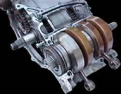
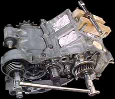
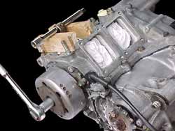
MC21R engine prepared for strip-down.
So the engine is spotlessly clean, and sat on the bench! All ports, water-ways, and oil galleries are blanked off, so you can get down to the job of dismantling it. Normally we would advise you to get the notebook and/or digital camera out at this point, and start to record specific steps as you proceed through the job, but we've taken care of that aspect for you already!
The dismantling and rebuild procedure can be applied to any year or model NSR, the only significant difference between the various types is the clutch; wet on all MC16's, MC18 Mk1's (R2J/R4J), this includes the Mk1 R4J SP, and all other 'R' models; dry on all other SE and SP models.
| Note: | Although visually different, the Mk1 hexagonal barrels are not too dissimilar to the Mk2 round barrels. The port timing and port sizes are different through each model, but they are interchangeable, unlike the clutch components where 'dry' components and 'wet' components must not be mixed! |

To make the unit more manageable, start by removing the barrels. They are surprisingly heavy chunks of aluminium, and manipulating the crank case will be a lot easier with them removed! There are a few things to consider when removing the barrels:
If you are just replacing the crank or crank seals and the top end is serviceable, then you need to keep each piston and ring set with its' corresponding barrel. Also, if the intention is to leave the top end 'as-is', the heads DO NOT need removing! This alone will save you about $30 in head gaskets!!
It is however adviseable to remove the cylinder heads for "de-coking" (removing carbon deposits) as this will give you the opportunity to check them for any signs of damage caused by detonation. The heads, like the pistons, can give you a very accurate reading of jet settings. We also recommend taking this opportunity to extract the RC Valves for cleaning and to check their operation.
The barrels will almost certainly be reluctant to separate from the crankcases! Unscrew the 4 cylinder retaining nuts and then, with a rubber mallet, in an upwards motion, strike the top of the cylinder near the joint with the cylinder head. Tap around each 'corner' of the barrel; don't be afraid to strike it with a little vigor!
| NEVER TRY TO PRISE THE BARREL AWAY FROM THE CRANKCASE. THIS WILL INEVITABLY DESTROY THE MATING SURFACES & RENDER BOTH THE ENGINE CASES AND THE BARRELS USELESS! |
Try not to twist the barrel as you lift it clear of the crankcase so as to minimise the possibility of damage to the rings. As each barrels is removed, remove its' corresponding piston. This will help to avoid inadvertently damaging it and also prevent mixing them up.
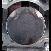
As demonstrated in these images, the piston was in good serviceable order. A little 'blow-by' can be observed above the gudgeon (wrist) pin but this can be expected.
 nose pliers to extract the circlips...")
From the carbon pattern on the piston crown, you can not only see the jetting is good, but also that the shape of the ports is working well! You can clearly see the uniform shape of the combusted charge. Later the rings will be 'gapped' to check their tollerance.
The next step is to remove the clutch and flywheel/stator assemblies. Start by removing the clutch cover. Pay special attention to the thin shim on the water pump drive shaft as this can easily stick to the clutch cover as it is removed and then get mislaid!


This is an 'R' model MC21 engine, and with the cover removed, you will be presented with a view of the clutch cover and its' 5 M6 retaining bolts, the kick-start shaft and pinion, and the primary drive gear on the end of the crank. This view will be similar on all MC16's, MC18 Mk1's (including the R4J SP), and all MC18 Mk2 and MC28 'R' models.
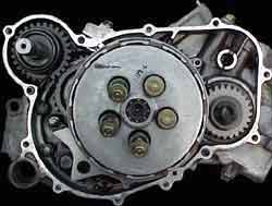
The dry clutch models differ in that the clutch pressure plate can be accessed without the necessity of removing the engine casing, and therefore without draining the transmission oil.
Slacken the 5 M6 retaining bolts and remove the pressure plate. On both dry and wet clutch models, carefully remove the pushrod spacer and ball bearing, then remove the steel and friction clutch plates, noting their order.

| Note: | The wet clutch uses 2 specially shaped steel rings closest to the hub. Pay special attention to their orientation. These are "judder springs" and help perform a similar job to the "damper rubbers" on the inner friction plate on the dry clutch models, smoothing the engagement of the transmission as the clutch lever is released. |
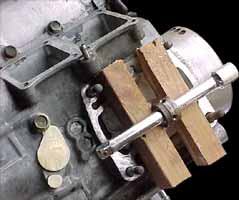
The 20mm centre lock-nut is fairly easy to remove, but a special tool is needed to lock the hub. This can easily be fabricated from 2 old steel plates spot welded together, and a handle then welded on to apply leverage in the opposite direction to the force on the nut. This tool can then be used for removing and replacing the centre lock-nut.
Special fabricated clutch holder.
This method and tool can be used for both wet and dry clutch models. The clutch centre lock-nut is re-useable, although it is recommended that it is replaced each time.

![]()

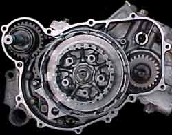
The clutch "hub" and "basket" can now be removed, and the pushrod withdrawn. The basket runs on 2 needle roller bearings; which too can be removed.
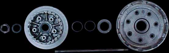
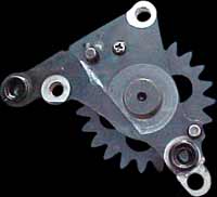
The image above shows the main components of the "R" clutch. The significant difference on the dry clutch models is the secondary gear. On the "R" model, the secondary gear is permanently attached directly to the clutch basket, and the whole assembly is housed within the transmission cover. On the dry clutch models the gear and basket are bolted together, and sandwich an oil seal. The secondary gear is housed behind the transmission cover, while the other components are accessible outside the main casings.
The final component to facilitate the removal of the crank on this side of the motor is the drive gear for the transmission oil pump, but while still assembled in the cases, now is a good time to remove the primary gear from the end of the crankshaft.
![]()
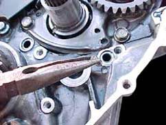
As the top end has already been removed, locking the crankshaft is a simple procedure. Pass a close fitting bar (a 3/8" drive extension bar is ideal) through a con-rod small-end eye and support it on two wooden blocks placed across the crank-case mouth.* Turn the crank until it locks, and then remove the primary drive retaining bolt and the washer behind it. While the crankshaft is locked, use this opportunity to remove the flywheel retaing bolt too.
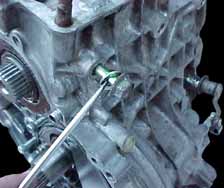
After removing the retaing bolt and its washer, unscrew the ignition pulser (pick-up) coil retaining clips and remove the coils and their wiring harness. Then, using only a "centre bolt" flywheel puller as shown in the diagram below, release the flywheel from the crankshaft taper. The puller can be obtained from NSR-WORLD.COM in our Marketplace.
| Note: | While this method of locking the crankshaft works well, it's not the ideal method! Although extremely unlikely, it can possibly distort the crank if excessive force is required to undo either the primary drive or the flywheel bolts. If possible, use a crankshaft locking tool. |
| Only the correct tool should be used to remove the flywheel. |
| NO OTHER METHOD OF FLYWHEEL REMOVAL, OTHER THAN WITH THE PULLER DEMONSTRATED, IS RECOMMENDED. |
![]()
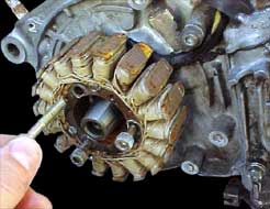
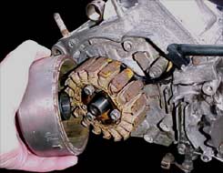
With the flywheel removed, unscrew the 3 M6 cap head screws retaining the alternator stator to the crankcase. Remove the Woodruff key from the crankshaft to prevent it being lost. (A new Honda crankshaft is not supplied with a new Woodruf key, so reuse the original one!)
Finally, back to the clutch side of the crankcase, and remove the oil/water pump drive gear.
Take note if the 2 o-ring seals and the 2 locating dowels as they are easily mislaid. The rubber o-rings should be replaced upon reassembly.
The crankcases are now ready to be split to allow the removal/replacement of the crank. There are 10 bolts securing the two crankcase halves, 5 M8 bolts on the underside, 1 M8 bolt and 4 M6 bolts on the top.
Note how the various bolts are different in length. All the bolts on the top crankcase have washers. The bolt behind the oil pump flange is the longest of the M8 bolts. On the underside, note the front bolt nearest the clutch/oil pump side, also has a washer.
Once the 10 bolts are removed, it is time to split the cases... it's that simple! The crankcase halves are bonded together with a silicone rubber typre adhesive, so the cases won't just fall apart! Some degree of levering will be needed, but under no circumstances should you try to prise apart any machined mating surfaces. Slight leverage can be applied to the underside of the inlet manifold, and on the lower cylinder, a thin block of soft wood can be used as a drift to tap the casing upwards. The soft-wood block will distort to the shape of the crankcase opening and allow a more even distribution of pressure thus preventing damage to the casing.
The genuine Honda crankcase seal is surprisingly easy to break, so if you are experiencing difficulty in separating the cases, double check you haven't inadvertantly left one bolt fastened!
With the top casing removed, the crank is ready to lift out.