
All NSR models share the same engine configuration; 90° V-twin, with a bore and stroke of 54.0 x 54.4 respectively, with only a slight rise in compression ratio throughout the years, and a swap from hexagonal shaped barrels to more conventional round ones on the MC21. This configuration is designated MC16E and appears on all models, regardless of age. Do not panic if you find the prefix MC16E on your MC28 cases!
The overall layout is based very heavily on the second generation (i.e. crankcase inducted) RS250 HRC race engine, in fact the RS250 motor will bolt straight into the NSR's frame using all the standard mounting points except the top rear. Also, a number of RS parts are interchangeable with the NSR's, but this will be covered at a later date.
Ports.
As mentioned earlier, the design of the engine lends itself considerably to the RS250, and this can clearly be seen in its port timing.
 |
The porting, both in shape and timing, although extremely similar to the RS, is Honda's best compromise between performance and tractability/reliability. The barrels can be ported to RS specification, but some components will undoubtedly suffer some longevity. The best improvements to make are by optimising the current configuration.
|
Although the port layout from the factory is already very good, both in terms of tune and finish, stock barrels can benefit greatly by some attention.
| Note: | Standard MC21SP port map. |
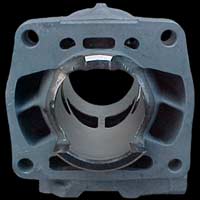
Using the above diagram of a typical mass production barrel, flaws in the layout can be clearly seen. The worst areas are the front transfer ports, closest to the exhaust port. One has a 3.5mm gap between it and the exhaust port, the other 4.5mm. The exhaust ports themselves and the bridge (the narrow strip between the two exhaust ports) is also generally a bad area, but is not something that can't be shown on a diagram such as this. This particular barrel had a bridge ranging from 4.8mm to 5.5mm, depending on where it was measured!
Tools.
The perfect tool for DIY porting has to be the Bosch Dremmel, with it's compact dimensions, and a wide variety of grinding attachments available from better hardware stores. The next best option is a good quality high speed electric drill with a 1 meter flexible attachment. Wolfcraft make just such an adapter, basically like a big speedo drive, with a 4mm chuck on one end. Bear in mind that you will be grinding constantly for some time, so an industrial rated drill is a much better option than a mail order £20 chocolate DIY drill! One final possibility, and undoubtedly both the best and most expensive option, is a dentists drill. These are used in conjunction with a foot pedal to vary the drive speed, and can also be used with an adapter to convert the rotating motion into a reciprocating (filing) motion, ideal for getting down into the thin narrow ports and for giving your front teeth that "movie star" gleam before you go out on a Saturday night! Next time you are having your teeth scaled, ask your friendly dentist if he has an old unit you can buy off him!!
Transfer ports.
|
||
To start, each port will benefit from a general clean up. The floor of some of the ports can be particularly uneven, and each needs to be matched to its opposite number in the layout. This is very important for even distribution of fuel mixture across the piston crown to assure an even burn. Grind each port to the dimensions of the larger of its opposite counterpart. Widening the ports to match each other, within reason, will be OK, but try to steer clear of grinding the top or bottom as this will effect the timing and could easily ruin the barrel, just grind the bare minimum to even them up and square them off.
Significantly raising the roof of the ports (or lowering them) is best left to a professional tuner unless you are fully confident in your skills or are working on spare barrels as an experiment!
Equalising the dimensions of all the ports like this will have a marked, positive effect on efficiency, and increased efficiency is what tuning is all about. Although 0.2mm here and 0.5mm there doesn't sound like much, very pleasing results can be obtained.
Another area that can often be improved is where the barrels meet the crankcase. Matching the two can greatly improve both flow and velocity, both essential to filling the combustion chamber. Matching the barrels to the cases is a slightly trickier job than just equalising the ports so will be covered at a later date, once we have the method documented.
To finish of the transfer ports, polish out any imperfections in the walls, and bevel off any sharp edges that the piston rings could get caught on.
Exhaust ports.
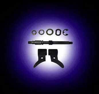
Before working on the exhaust port, the RC Valve should be removed. This is by no means an easy job, as odds are the assembly has never been apart before and is "coked" up. Once the pulley hardware is removed, the spindle is simply a press fit; the circlip below the oil seal does not hold the spindle in place. Difficulty in extracting it is purely down to carbon deposits. Copious amounts of carb cleaning spray can help loosen a stubborn valve.
|
||
|
||
Irregularities in the exhaust ports are usually the most apparent. The bridge is often very uneven and the barrel the measurements in the earlier diagram were taken from had a width ranging from 6mm down to 4.5mm in places. Cleaning the exhaust port up is an area where the greatest gains can be made. The bridge can be safely narrowed down to 4mm, with 3mm being the absolute maximum for reliability. Reducing the bridge this far is a job for a professional tuner though as it can cause it to expand under extreme conditions and pinch the piston causing seizure. A very narrow bridge is also susceptable to cracking if not warmed up steadily and allowed to cool properly. |
Make sure both the roof and base of each port is again level, but it is not recommended raising the top of the port any further than 27.8mm, the measurement used for the RS250. Finally make sure once again the walls are smoothly flowed. Do not grind the expansion chamber side, although enlarging the outlet side of the port can produce significant gains, this again is best left to a professional as the removal of too much metal here will ruin the barrel. |
|
The last job is to optimise the RC Valve. Setting up of the RC Valve is crucial to peak performance of the NSR250, and is covered later. After optimising the ports, and vigorously cleaning the barrel and RC Valve components, reassemble them. DO NOT use any form of abrasive paper on the power valve spindle, only clean it with a solvent, and if you must scrape it, use a only a blunt edge like a worn electrical screwdriver. You should find all the parts go back together very easily, and now they are clean and free, remove them periodically for cleaning! |
It is highly probable that the RC Valve will need reshaping, so once installed check it. Open the valve so the highest side is flush with the top edge of the exhaust port. The lower side then needs to be ground so it too sits flush to the exhaust port. 0.5mm could be ground off of one side on the example barrel. JHA express considerable emphasis on correct setting of the RC Valve on the RS motors, something that the NSR will benefit from too.
Supplementary modifications.
A trick modification for MC21's and 28's is the replacement of the stock lower cylinder head with an HRC kit. The stock NSR's lower head has an offset spark plug position, consequently producing an inefficient 'flame path'. Replacing the lower head with an upper one gives the plug a more central location, but you will run into clearance issues and therefore need to run a short RS250 style plug and cap.
| Note: | The MC28 HRC kit is nothing more than a stock top head and different radiator hose. Special heads were produced by HRC for all other models, with the 1988 and 1989 MC18's having true centre mounted plugs. |
An HRC hose is required to plumb in the head, part# 19508-NKD-980 (1) or 19509-NKD-980 (2), depending on the radiator used. Use hose number (1) for the kit (i.e. HRC) radiator, and hose (2) for the standard radiator. You will also find that two of the studs need changing as one is just long enough, but the other is not!
The benefit of this modification is the increased efficiency of the front cylinder, probably accounting for the greater variance in the jet sizes recommended by HRC and Jha to those recommended by M-Max. (See the table in the carburation section.)
There is no benefit in changing the MC18's head configuration.
The difference between a piped and jetted motor with optimised* porting could be as much as 5hp.
*Optimised porting only reworks the standard layout; traditional porting (enlarging and reshaping of the ports) could yield much higher gains but needs to be carried out by a professional and will greatly increase the maintenance schedule of the engine, something not necessarily practical for a street bike. NSR-WORLD.COM can offer port optimisation and porting through the Performance section.
Clutch.
Often overlooked, the clutch plays an extremely important role transmitting the drive from the engine to the rear wheel. Upgrading it is a simple task! The obvious upgrade for an R model is to exchange the whole 'wet' assembly for a dry clutch from an SE or SP*.
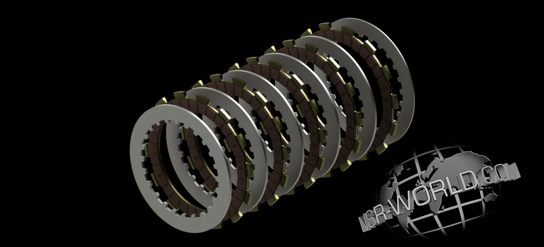
For the SE/SP models, an even more simple upgrade is available! Simply exchange the 2mm steel plate (part 10) closest to the engine with a 2.9mm plate (part 9) as used throughout the rest of the assembly. Using the thicker plate effectively preloads the clutch springs, raising their 'rate' in the same way adjusting preload does on suspension. HRC has not specified uprated clutch springs since the F3 MC18 and many race bikes still use stock springs. However, Jha and EBC both list uprated springs if you still feel they are required. Although we at ![]() have used both Jha and EBC springs in the past, the Jha variants are preferred as the EBC gave a very heavy action at the lever.
have used both Jha and EBC springs in the past, the Jha variants are preferred as the EBC gave a very heavy action at the lever.
*Some riders and racers to prefer the 'feel' of a wet clutch to a dry one, this is entirely personal preference; in our opinion the dry clutch is a better system. The benefit of the dry clutch is the ease of changing worn components without the need to drain the transmission oil, and as the plates wear, the resulting debris does not contaminate the oil either.
F3 Transmission.
The F3 transmission is effectively a pre 1993 HRC RS250* unit that slots straight into the NSR's casing! As well as the longer 1st gear, giving much closer ratios throughout the rest of the 'box, the gears are undercut for closer, more accurate meshing. There is also a huge range of ratios available to suit any type of track or state of tune.
| Note: | While the RS250 transmissions do fit, there are minor differences across model years between both the RS and the NSR. Some degree of "mix'n'match" will be required if using an RS transmission. |
The 1987 NSR250 MC16 TT-F3 transmission is most similar to the RS250 NF5. It comes complete with a different engine casing/clutch cover, and uses the the NF5 primary gears, basket, hub, and plates, which are all different to the NSR items. (And substantially lighter.) It's the best kit you can fit, and with a little work, can be retro-fitted to 88~97 models.
RC Valve adjustment.
As mentioned before, setting of the RC Valve is absolutely crucial to peak performance of the NSR, and a Valve too far open can be as disruptive as one not open enough! Follow these simple steps to adjust it:
With the kill switch set to the run position, turn the ignition on with the key/card. Allow the Valve to cycle to the start setting. Now switch the ignition back off with the key/card. Unplug the throttle position sensor (T.P.S), located on the inside of the right frame rail under the air solenoid block, and switch the ignition back on. The servo will rotate to the "hi" open position. Once again, turn the ignition off. Adjust the cables at the pulley end so the pointer aligns with the mark on the back plate as shown in the diagram below.
|
Alternatively, slacken off the cables completely and fit a dowel into (A), something like a drill bit (make sure it's a snug fit) is ideal, this is how the factory aligns the valve and is the quickest way to adjust it, but not necessarily the most accurate, and readjust the play out of the cables.
With the ignition still off, and both valves adjusted (and the dowels removed if using that method!!), tighten the locknuts and reconnect the T.P.S multi-plug. Switch the ignition back on and the servo will rotate back to the start position and you're ready to go!!
| NSR-WORLD.COM ACCEPTS NO RESPONSIBILITY FOR ANY MECHANICAL OR PERSONAL CONSEQUENCE ARISING FROM THE INTERPRETATION OF THIS DOCUMENT OR THE MODIFICATION OF ANY COMPONENT REFERRED TO WITHIN IT, AND RECOMMENDS THAT ANY MODIFICATION ONLY BE CARRIED OUT BY A SUITABLY QUALIFIED MOTORCYCLE MECHANIC. |
| Note: | Please note that it may be illegal to modify certain components in some countries and may require amendments to insurance policies in others. |
![]()

![]()